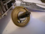
In this group of pics you can see the coiled flat spring which supplies the power to the lock. It is held in the round case visible in of the previous pictures posted. In another, the click stop mechanism can be seen. This allows the coiled spring to be wound up, storing the energy. It cannot be seen at all when the lock is assembled and sits right atop the spring itself. When assembled, the winding shaft engages the inner end of the spring by a protruding notch which I see now I failed to show when I took the picture. It is on the back side of the shaft. In the third picture is the Geneva stop which is located on the outer backside of the spring housing. All except one of the “teeth” are concave on this geared wheel, which just freewheels, being attached to the case by a shoulder screw. The one convex tooth will stop the wheel from turning in turn stopping the winding shaft. This acts to limit the maximum turns that can be applied to the movement preventing overwinding the spring as well as limiting or rather preventing the spring from fully unwinding. This is known as reserve power, supplying the necessary pressure to ensure unlocking.